16 KiB
Open vSwitch: Provider networks
This architecture example provides layer-2 connectivity between
instances and the physical network infrastructure using VLAN (802.1q)
tagging. It supports one untagged (flat) network and up to 4095 tagged
(VLAN) networks. The actual quantity of VLAN networks depends on the
physical network infrastructure. For more information on provider
networks, see intro-os-networking-provider.
Warning
Linux distributions often package older releases of Open vSwitch that can introduce issues during operation with the Networking service. We recommend using at least the latest long-term stable (LTS) release of Open vSwitch for the best experience and support from Open vSwitch. See http://www.openvswitch.org for available releases and the installation instructions for more details.
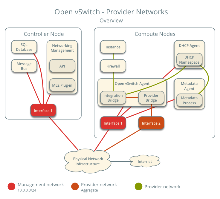
Prerequisites
One controller node with the following components:
- Two network interfaces: management and provider.
- OpenStack Networking server service and ML2 plug-in.
Two compute nodes with the following components:
- Two network interfaces: management and provider.
- OpenStack Networking Open vSwitch (OVS) layer-2 agent, DHCP agent, metadata agent, and any dependencies including OVS.
Note
Larger deployments typically deploy the DHCP and metadata agents on a subset of compute nodes to increase performance and redundancy. However, too many agents can overwhelm the message bus. Also, to further simplify any deployment, you can omit the metadata agent and use a configuration drive to provide metadata to instances.
Architecture
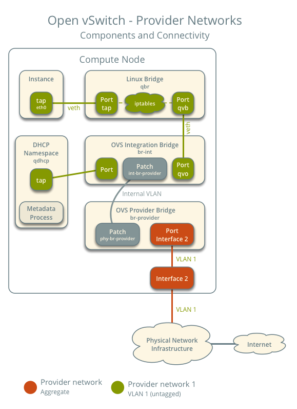
The following figure shows components and connectivity for one untagged (flat) network. In this particular case, the instance resides on the same compute node as the DHCP agent for the network. If the DHCP agent resides on another compute node, the latter only contains a DHCP namespace with a port on the OVS integration bridge.
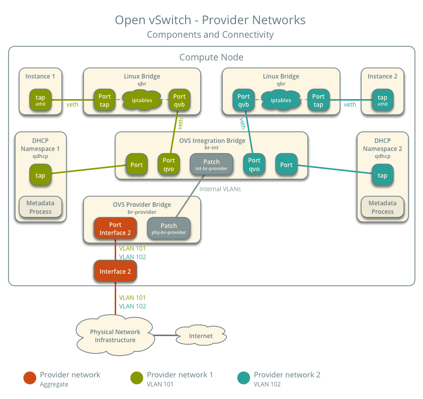
The following figure describes virtual connectivity among components for two tagged (VLAN) networks. Essentially, all networks use a single OVS integration bridge with different internal VLAN tags. The internal VLAN tags almost always differ from the network VLAN assignment in the Networking service. Similar to the untagged network case, the DHCP agent may reside on a different compute node.
Note
These figures omit the controller node because it does not handle instance network traffic.
Example configuration
Use the following example configuration as a template to deploy provider networks in your environment.
Controller node
Install the Networking service components that provide the
neutron-serverservice and ML2 plug-in.In the
neutron.conffile:Configure common options:
Disable service plug-ins because provider networks do not require any. However, this breaks portions of the dashboard that manage the Networking service. See the latest Install Tutorials and Guides for more information.
[DEFAULT]
service_plugins =
Enable two DHCP agents per network so both compute nodes can provide DHCP service provider networks.
[DEFAULT]
dhcp_agents_per_network = 2
If necessary,
configure MTU <config-mtu>.
In the
ml2_conf.inifile:Configure drivers and network types:
[ml2]
type_drivers = flat,vlan
tenant_network_types =
mechanism_drivers = openvswitch
extension_drivers = port_security
Configure network mappings:
[ml2_type_flat]
flat_networks = provider

[ml2_type_vlan]
network_vlan_ranges = provider
Note
The
tenant_network_typesoption contains no value because the architecture does not support self-service networks.Note
The
providervalue in thenetwork_vlan_rangesoption lacks VLAN ID ranges to support use of arbitrary VLAN IDs.
Populate the database.
# su -s /bin/sh -c "neutron-db-manage --config-file /etc/neutron/neutron.conf \
  --config-file /etc/neutron/plugins/ml2/ml2_conf.ini upgrade head" neutron
Start the following services:
- Server
Compute nodes
Install the Networking service OVS layer-2 agent, DHCP agent, and metadata agent.
Install OVS.
In the
neutron.conffile, configure common options:In the
openvswitch_agent.inifile, configure the OVS agent:[ovs] bridge_mappings = provider:br-provider [securitygroup] firewall_driver = iptables_hybridIn the
dhcp_agent.inifile, configure the DHCP agent:[DEFAULT] interface_driver = openvswitch enable_isolated_metadata = True force_metadata = TrueNote
The
force_metadataoption forces the DHCP agent to provide a host route to the metadata service on169.254.169.254regardless of whether the subnet contains an interface on a router, thus maintaining similar and predictable metadata behavior among subnets.In the
metadata_agent.inifile, configure the metadata agent:[DEFAULT] nova_metadata_host = controller metadata_proxy_shared_secret = METADATA_SECRETThe value of
METADATA_SECRETmust match the value of the same option in the[neutron]section of thenova.conffile.Start the following services:
- OVS
Create the OVS provider bridge
br-provider:$ ovs-vsctl add-br br-providerAdd the provider network interface as a port on the OVS provider bridge
br-provider:$ ovs-vsctl add-port br-provider PROVIDER_INTERFACEReplace
PROVIDER_INTERFACEwith the name of the underlying interface that handles provider networks. For example,eth1.Start the following services:
- OVS agent
- DHCP agent
- Metadata agent
Verify service operation
Source the administrative project credentials.
Verify presence and operation of the agents:
$ openstack network agent list
+--------------------------------------+--------------------+----------+-------------------+-------+-------+---------------------------+
| ID                                   | Agent Type         | Host     | Availability Zone | Alive | State | Binary                    |
+--------------------------------------+--------------------+----------+-------------------+-------+-------+---------------------------+
| 1236bbcb-e0ba-48a9-80fc-81202ca4fa51 | Metadata agent     | compute2 | None              | True  | UP    | neutron-metadata-agent    |
| 457d6898-b373-4bb3-b41f-59345dcfb5c5 | Open vSwitch agent | compute2 | None              | True  | UP    | neutron-openvswitch-agent |
| 71f15e84-bc47-4c2a-b9fb-317840b2d753 | DHCP agent         | compute2 | nova              | True  | UP    | neutron-dhcp-agent        |
| a6c69690-e7f7-4e56-9831-1282753e5007 | Metadata agent     | compute1 | None              | True  | UP    | neutron-metadata-agent    |
| af11f22f-a9f4-404f-9fd8-cd7ad55c0f68 | DHCP agent         | compute1 | nova              | True  | UP    | neutron-dhcp-agent        |
| bcfc977b-ec0e-4ba9-be62-9489b4b0e6f1 | Open vSwitch agent | compute1 | None              | True  | UP    | neutron-openvswitch-agent |
+--------------------------------------+--------------------+----------+-------------------+-------+-------+---------------------------+
Create initial networks
Verify network operation
Network traffic flow
North-south
- The instance resides on compute node 1 and uses provider network 1.
- The instance sends a packet to a host on the Internet.
The following steps involve compute node 1.
- The instance interface (1) forwards the packet to the security group
bridge instance port (2) via
vethpair. - Security group rules (3) on the security group bridge handle firewalling and connection tracking for the packet.
- The security group bridge OVS port (4) forwards the packet to the
OVS integration bridge security group port (5) via
vethpair. - The OVS integration bridge adds an internal VLAN tag to the packet.
- The OVS integration bridge
int-br-providerpatch port (6) forwards the packet to the OVS provider bridgephy-br-providerpatch port (7). - The OVS provider bridge swaps the internal VLAN tag with actual VLAN tag 101.
- The OVS provider bridge provider network port (8) forwards the packet to the physical network interface (9).
- The physical network interface forwards the packet to the physical network infrastructure switch (10).
The following steps involve the physical network infrastructure:
- The switch removes VLAN tag 101 from the packet and forwards it to the router (11).
- The router routes the packet from the provider network (12) to the external network (13) and forwards the packet to the switch (14).
- The switch forwards the packet to the external network (15).
- The external network (16) receives the packet.
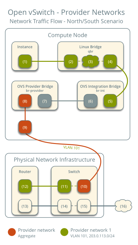
Note
Return traffic follows similar steps in reverse.
East-west scenario 1: Instances on the same network
Instances on the same network communicate directly between compute nodes containing those instances.
- Instance 1 resides on compute node 1 and uses provider network 1.
- Instance 2 resides on compute node 2 and uses provider network 1.
- Instance 1 sends a packet to instance 2.
The following steps involve compute node 1:
- The instance 1 interface (1) forwards the packet to the security
group bridge instance port (2) via
vethpair. - Security group rules (3) on the security group bridge handle firewalling and connection tracking for the packet.
- The security group bridge OVS port (4) forwards the packet to the
OVS integration bridge security group port (5) via
vethpair. - The OVS integration bridge adds an internal VLAN tag to the packet.
- The OVS integration bridge
int-br-providerpatch port (6) forwards the packet to the OVS provider bridgephy-br-providerpatch port (7). - The OVS provider bridge swaps the internal VLAN tag with actual VLAN tag 101.
- The OVS provider bridge provider network port (8) forwards the packet to the physical network interface (9).
- The physical network interface forwards the packet to the physical network infrastructure switch (10).
The following steps involve the physical network infrastructure:
- The switch forwards the packet from compute node 1 to compute node 2 (11).
The following steps involve compute node 2:
- The physical network interface (12) forwards the packet to the OVS provider bridge provider network port (13).
- The OVS provider bridge
phy-br-providerpatch port (14) forwards the packet to the OVS integration bridgeint-br-providerpatch port (15). - The OVS integration bridge swaps the actual VLAN tag 101 with the internal VLAN tag.
- The OVS integration bridge security group port (16) forwards the packet to the security group bridge OVS port (17).
- Security group rules (18) on the security group bridge handle firewalling and connection tracking for the packet.
- The security group bridge instance port (19) forwards the packet to
the instance 2 interface (20) via
vethpair.
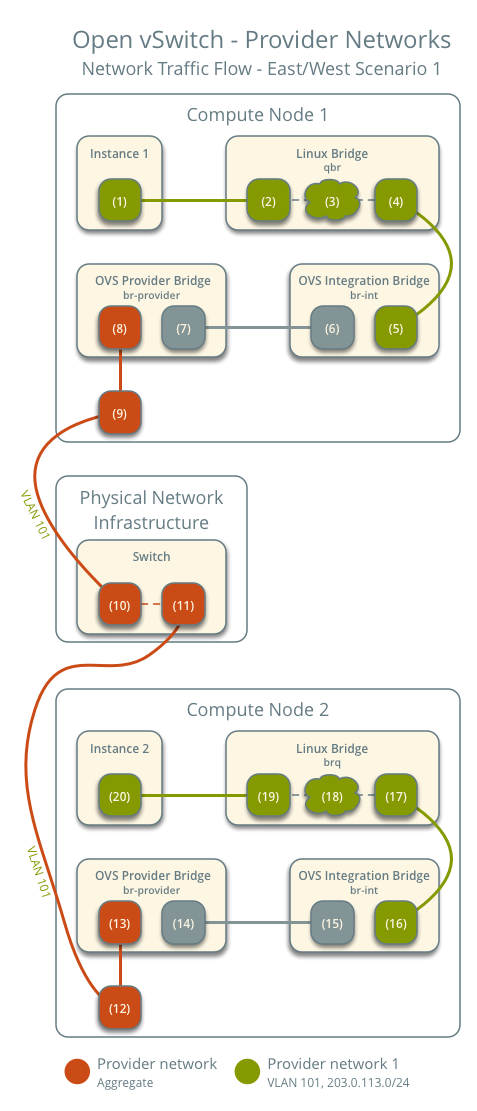
Note
Return traffic follows similar steps in reverse.
East-west scenario 2: Instances on different networks
Instances communicate via router on the physical network infrastructure.
- Instance 1 resides on compute node 1 and uses provider network 1.
- Instance 2 resides on compute node 1 and uses provider network 2.
- Instance 1 sends a packet to instance 2.
Note
Both instances reside on the same compute node to illustrate how VLAN tagging enables multiple logical layer-2 networks to use the same physical layer-2 network.
The following steps involve the compute node:
- The instance 1 interface (1) forwards the packet to the security
group bridge instance port (2) via
vethpair. - Security group rules (3) on the security group bridge handle firewalling and connection tracking for the packet.
- The security group bridge OVS port (4) forwards the packet to the
OVS integration bridge security group port (5) via
vethpair. - The OVS integration bridge adds an internal VLAN tag to the packet.
- The OVS integration bridge
int-br-providerpatch port (6) forwards the packet to the OVS provider bridgephy-br-providerpatch port (7). - The OVS provider bridge swaps the internal VLAN tag with actual VLAN tag 101.
- The OVS provider bridge provider network port (8) forwards the packet to the physical network interface (9).
- The physical network interface forwards the packet to the physical network infrastructure switch (10).
The following steps involve the physical network infrastructure:
- The switch removes VLAN tag 101 from the packet and forwards it to the router (11).
- The router routes the packet from provider network 1 (12) to provider network 2 (13).
- The router forwards the packet to the switch (14).
- The switch adds VLAN tag 102 to the packet and forwards it to compute node 1 (15).
The following steps involve the compute node:
- The physical network interface (16) forwards the packet to the OVS provider bridge provider network port (17).
- The OVS provider bridge
phy-br-providerpatch port (18) forwards the packet to the OVS integration bridgeint-br-providerpatch port (19). - The OVS integration bridge swaps the actual VLAN tag 102 with the internal VLAN tag.
- The OVS integration bridge security group port (20) removes the internal VLAN tag and forwards the packet to the security group bridge OVS port (21).
- Security group rules (22) on the security group bridge handle firewalling and connection tracking for the packet.
- The security group bridge instance port (23) forwards the packet to
the instance 2 interface (24) via
vethpair.
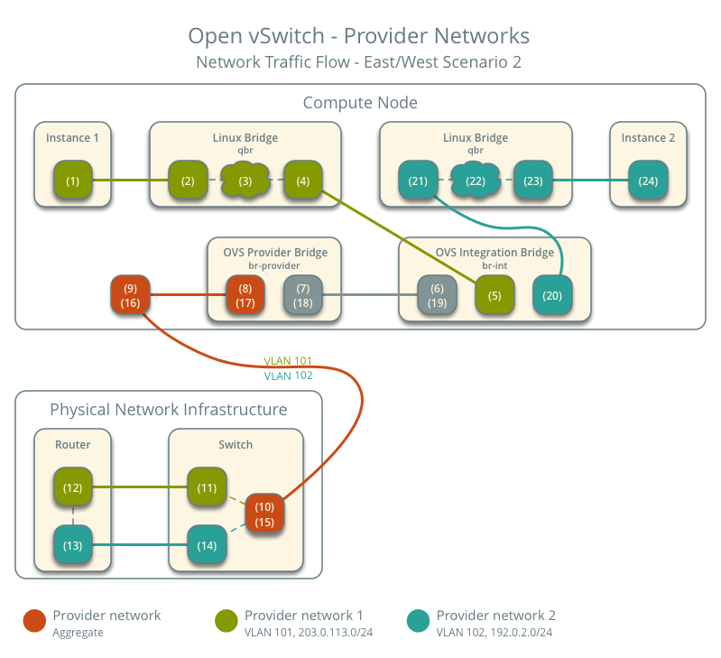
Note
Return traffic follows similar steps in reverse.