17 KiB
Linux bridge: Self-service networks
This architecture example augments deploy-lb-provider to support a nearly limitless
quantity of entirely virtual networks. Although the Networking service
supports VLAN self-service networks, this example focuses on VXLAN
self-service networks. For more information on self-service networks,
see intro-os-networking-selfservice.
Note
The Linux bridge agent lacks support for other overlay protocols such as GRE and Geneve.
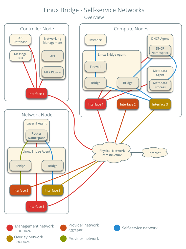
Prerequisites
Add one network node with the following components:
- Three network interfaces: management, provider, and overlay.
- OpenStack Networking Linux bridge layer-2 agent, layer-3 agent, and any
-
dependencies.
Modify the compute nodes with the following components:
- Add one network interface: overlay.
Note
You can keep the DHCP and metadata agents on each compute node or move them to the network node.
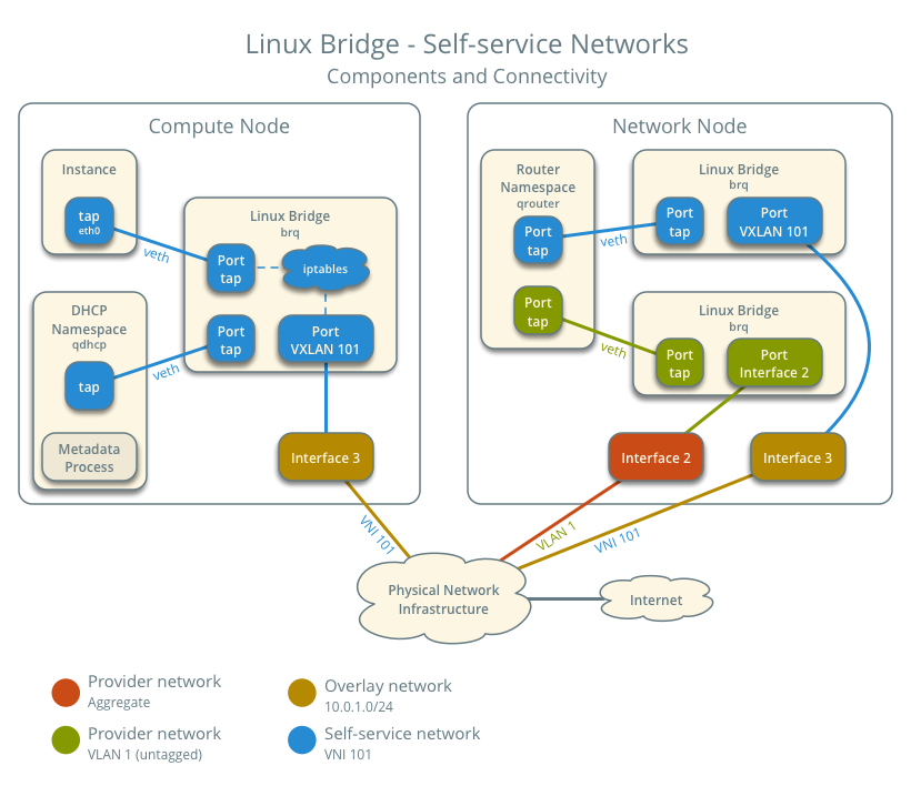
Architecture
The following figure shows components and connectivity for one self-service network and one untagged (flat) provider network. In this particular case, the instance resides on the same compute node as the DHCP agent for the network. If the DHCP agent resides on another compute node, the latter only contains a DHCP namespace and Linux bridge with a port on the overlay physical network interface.
Example configuration
Use the following example configuration as a template to add support for self-service networks to an existing operational environment that supports provider networks.
Controller node
- In the
neutron.conffile:Enable routing and allow overlapping IP address ranges.
[DEFAULT]
service_plugins = router
allow_overlapping_ips = True
- In the
ml2_conf.inifile:Add
vxlanto type drivers and project network types.[ml2] type_drivers = flat,vlan,vxlan tenant_network_types = vxlanEnable the layer-2 population mechanism driver.
[ml2]
mechanism_drivers = linuxbridge,l2population
Configure the VXLAN network ID (VNI) range.
[ml2_type_vxlan]
vni_ranges = VNI_START:VNI_END
Replace
VNI_STARTandVNI_ENDwith appropriate numerical values.
- Restart the following services:
- Server
Network node
Install the Networking service layer-3 agent.
In the
neutron.conffile, configure common options:In the
linuxbridge_agent.inifile, configure the layer-2 agent.[linux_bridge] physical_interface_mappings = provider:PROVIDER_INTERFACE [vxlan] enable_vxlan = True l2_population = True local_ip = OVERLAY_INTERFACE_IP_ADDRESS [securitygroup] firewall_driver = iptablesWarning
By default, Linux uses UDP port
8472for VXLAN tunnel traffic. This default value doesn't follow the IANA standard, which assigned UDP port4789for VXLAN communication. As a consequence, if this node is part of a mixed deployment, where nodes with both OVS and Linux bridge must communicate over VXLAN tunnels, it is recommended that a line containingudp_dstport = 4789be added to the [vxlan] section of all the Linux bridge agents. OVS follows the IANA standard.Replace
PROVIDER_INTERFACEwith the name of the underlying interface that handles provider networks. For example,eth1.Replace
OVERLAY_INTERFACE_IP_ADDRESSwith the IP address of the interface that handles VXLAN overlays for self-service networks.In the
l3_agent.inifile, configure the layer-3 agent.[DEFAULT] interface_driver = linuxbridgeStart the following services:
- Linux bridge agent
- Layer-3 agent
Compute nodes
In the
linuxbridge_agent.inifile, enable VXLAN support including layer-2 population.[vxlan] enable_vxlan = True l2_population = True local_ip = OVERLAY_INTERFACE_IP_ADDRESSWarning
By default, Linux uses UDP port
8472for VXLAN tunnel traffic. This default value doesn't follow the IANA standard, which assigned UDP port4789for VXLAN communication. As a consequence, if this node is part of a mixed deployment, where nodes with both OVS and Linux bridge must communicate over VXLAN tunnels, it is recommended that a line containingudp_dstport = 4789be added to the [vxlan] section of all the Linux bridge agents. OVS follows the IANA standard.Replace
OVERLAY_INTERFACE_IP_ADDRESSwith the IP address of the interface that handles VXLAN overlays for self-service networks.Restart the following services:
- Linux bridge agent
Verify service operation
Source the administrative project credentials.
Verify presence and operation of the agents.
$ openstack network agent list
+--------------------------------------+--------------------+----------+-------------------+-------+-------+---------------------------+
| ID                                   | Agent Type         | Host     | Availability Zone | Alive | State | Binary                    |
+--------------------------------------+--------------------+----------+-------------------+-------+-------+---------------------------+
| 09de6af6-c5f1-4548-8b09-18801f068c57 | Linux bridge agent | compute2 | None              | True  | UP    | neutron-linuxbridge-agent |
| 188945d1-9e70-4803-a276-df924e0788a4 | Linux bridge agent | compute1 | None              | True  | UP    | neutron-linuxbridge-agent |
| e76c440d-d5f6-4316-a674-d689630b629e | DHCP agent         | compute1 | nova              | True  | UP    | neutron-dhcp-agent        |
| e67367de-6657-11e6-86a4-931cd04404bb | DHCP agent         | compute2 | nova              | True  | UP    | neutron-dhcp-agent        |
| e8174cae-6657-11e6-89f0-534ac6d0cb5c | Metadata agent     | compute1 | None              | True  | UP    | neutron-metadata-agent    |
| ece49ec6-6657-11e6-bafb-c7560f19197d | Metadata agent     | compute2 | None              | True  | UP    | neutron-metadata-agent    |
| 598f6357-4331-4da5-a420-0f5be000bec9 | L3 agent           | network1 | nova              | True  | UP    | neutron-l3-agent          |
| f4734e0f-bcd5-4922-a19d-e31d56b0a7ae | Linux bridge agent | network1 | None              | True  | UP    | neutron-linuxbridge-agent |
+--------------------------------------+--------------------+----------+-------------------+-------+-------+---------------------------+
Create initial networks
Verify network operation
Network traffic flow
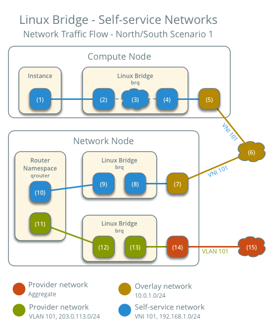
North-south scenario 1: Instance with a fixed IP address
For instances with a fixed IPv4 address, the network node performs SNAT on north-south traffic passing from self-service to external networks such as the Internet. For instances with a fixed IPv6 address, the network node performs conventional routing of traffic between self-service and external networks.
- The instance resides on compute node 1 and uses self-service network 1.
- The instance sends a packet to a host on the Internet.
The following steps involve compute node 1:
- The instance interface (1) forwards the packet to the self-service
bridge instance port (2) via
vethpair. - Security group rules (3) on the self-service bridge handle firewalling and connection tracking for the packet.
- The self-service bridge forwards the packet to the VXLAN interface (4) which wraps the packet using VNI 101.
- The underlying physical interface (5) for the VXLAN interface forwards the packet to the network node via the overlay network (6).
The following steps involve the network node:
- The underlying physical interface (7) for the VXLAN interface forwards the packet to the VXLAN interface (8) which unwraps the packet.
- The self-service bridge router port (9) forwards the packet to the
self-service network interface (10) in the router namespace.
- For IPv4, the router performs SNAT on the packet which changes the source IP address to the router IP address on the provider network and sends it to the gateway IP address on the provider network via the gateway interface on the provider network (11).
- For IPv6, the router sends the packet to the next-hop IP address, typically the gateway IP address on the provider network, via the provider gateway interface (11).
- The router forwards the packet to the provider bridge router port (12).
- The VLAN sub-interface port (13) on the provider bridge forwards the packet to the provider physical network interface (14).
- The provider physical network interface (14) adds VLAN tag 101 to the packet and forwards it to the Internet via physical network infrastructure (15).
Note
Return traffic follows similar steps in reverse. However, without a floating IPv4 address, hosts on the provider or external networks cannot originate connections to instances on the self-service network.
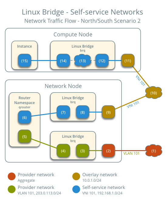
North-south scenario 2: Instance with a floating IPv4 address
For instances with a floating IPv4 address, the network node performs SNAT on north-south traffic passing from the instance to external networks such as the Internet and DNAT on north-south traffic passing from external networks to the instance. Floating IP addresses and NAT do not apply to IPv6. Thus, the network node routes IPv6 traffic in this scenario.
- The instance resides on compute node 1 and uses self-service network 1.
- A host on the Internet sends a packet to the instance.
The following steps involve the network node:
- The physical network infrastructure (1) forwards the packet to the provider physical network interface (2).
- The provider physical network interface removes VLAN tag 101 and forwards the packet to the VLAN sub-interface on the provider bridge.
- The provider bridge forwards the packet to the self-service router
gateway port on the provider network (5).
- For IPv4, the router performs DNAT on the packet which changes the destination IP address to the instance IP address on the self-service network and sends it to the gateway IP address on the self-service network via the self-service interface (6).
- For IPv6, the router sends the packet to the next-hop IP address, typically the gateway IP address on the self-service network, via the self-service interface (6).
- The router forwards the packet to the self-service bridge router port (7).
- The self-service bridge forwards the packet to the VXLAN interface (8) which wraps the packet using VNI 101.
- The underlying physical interface (9) for the VXLAN interface forwards the packet to the network node via the overlay network (10).
The following steps involve the compute node:
- The underlying physical interface (11) for the VXLAN interface forwards the packet to the VXLAN interface (12) which unwraps the packet.
- Security group rules (13) on the self-service bridge handle firewalling and connection tracking for the packet.
- The self-service bridge instance port (14) forwards the packet to
the instance interface (15) via
vethpair.
Note
Egress instance traffic flows similar to north-south scenario 1, except SNAT changes the source IP address of the packet to the floating IPv4 address rather than the router IP address on the provider network.
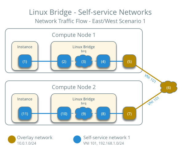
East-west scenario 1: Instances on the same network
Instances with a fixed IPv4/IPv6 or floating IPv4 address on the same network communicate directly between compute nodes containing those instances.
By default, the VXLAN protocol lacks knowledge of target location and
uses multicast to discover it. After discovery, it stores the location
in the local forwarding database. In large deployments, the discovery
process can generate a significant amount of network that all nodes must
process. To eliminate the latter and generally increase efficiency, the
Networking service includes the layer-2 population mechanism driver that
automatically populates the forwarding database for VXLAN interfaces.
The example configuration enables this driver. For more information, see
config-plugin-ml2.
- Instance 1 resides on compute node 1 and uses self-service network 1.
- Instance 2 resides on compute node 2 and uses self-service network 1.
- Instance 1 sends a packet to instance 2.
The following steps involve compute node 1:
- The instance 1 interface (1) forwards the packet to the self-service
bridge instance port (2) via
vethpair. - Security group rules (3) on the self-service bridge handle firewalling and connection tracking for the packet.
- The self-service bridge forwards the packet to the VXLAN interface (4) which wraps the packet using VNI 101.
- The underlying physical interface (5) for the VXLAN interface forwards the packet to compute node 2 via the overlay network (6).
The following steps involve compute node 2:
- The underlying physical interface (7) for the VXLAN interface forwards the packet to the VXLAN interface (8) which unwraps the packet.
- Security group rules (9) on the self-service bridge handle firewalling and connection tracking for the packet.
- The self-service bridge instance port (10) forwards the packet to
the instance 1 interface (11) via
vethpair.
Note
Return traffic follows similar steps in reverse.
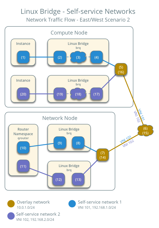
East-west scenario 2: Instances on different networks
Instances using a fixed IPv4/IPv6 address or floating IPv4 address communicate via router on the network node. The self-service networks must reside on the same router.
- Instance 1 resides on compute node 1 and uses self-service network 1.
- Instance 2 resides on compute node 1 and uses self-service network 2.
- Instance 1 sends a packet to instance 2.
Note
Both instances reside on the same compute node to illustrate how VXLAN enables multiple overlays to use the same layer-3 network.
The following steps involve the compute node:
- The instance 1 interface (1) forwards the packet to the self-service
bridge instance port (2) via
vethpair. - Security group rules (3) on the self-service bridge handle firewalling and connection tracking for the packet.
- The self-service bridge forwards the packet to the VXLAN interface (4) which wraps the packet using VNI 101.
- The underlying physical interface (5) for the VXLAN interface forwards the packet to the network node via the overlay network (6).
The following steps involve the network node:
- The underlying physical interface (7) for the VXLAN interface forwards the packet to the VXLAN interface (8) which unwraps the packet.
- The self-service bridge router port (9) forwards the packet to the self-service network 1 interface (10) in the router namespace.
- The router sends the packet to the next-hop IP address, typically the gateway IP address on self-service network 2, via the self-service network 2 interface (11).
- The router forwards the packet to the self-service network 2 bridge router port (12).
- The self-service network 2 bridge forwards the packet to the VXLAN interface (13) which wraps the packet using VNI 102.
- The physical network interface (14) for the VXLAN interface sends the packet to the compute node via the overlay network (15).
The following steps involve the compute node:
- The underlying physical interface (16) for the VXLAN interface sends the packet to the VXLAN interface (17) which unwraps the packet.
- Security group rules (18) on the self-service bridge handle firewalling and connection tracking for the packet.
- The self-service bridge instance port (19) forwards the packet to
the instance 2 interface (20) via
vethpair.
Note
Return traffic follows similar steps in reverse.